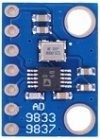
AD9833 module is a 0-12.5Mhz waveform generator with integral 25MHz crystal oscillator, the output frequency is set by the SPI controlled divider of the AD9833. A DAC shapes the sine and triangle waveforms, amplitude is 600mV. Squarewave amplitude is 5V. The Arduino drives the AD9833 using SPI. The Frequency in the AD9833 is selected by 28 bit value which gives about 0.1Hz resolution, the Arduino and B4R limit of Ulong numbers allows accuracy of about 1%.
Pushbutton WAVEFORM selects between Sine, Triangle (300mV) or Squarewave (5V). Digit pushbutton selects the digit to set, UP pushbutton increments the digit.
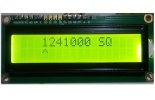
The LCD of 16x2 display the High and Low Frequencies. The 16x2 LCD module has to be HD44780 compatible.
AD9833 from eBay: https://www.ebay.co.uk/
Pushbutton WAVEFORM selects between Sine, Triangle (300mV) or Squarewave (5V). Digit pushbutton selects the digit to set, UP pushbutton increments the digit.
The LCD of 16x2 display the High and Low Frequencies. The 16x2 LCD module has to be HD44780 compatible.
AD9833 from eBay: https://www.ebay.co.uk/
ad9833:
Sub Process_Globals
    Public Serial1 As Serial
    Private tmr As Timer
    Public lcd As LiquidCrystal
    Public fsync As Pin
    Public sdata As Pin
    Public sclk As Pin
    Public digit As Pin
    Public wave As Pin
    Public up As Pin
    Public d(7) As Double
    Public  wf, j, pos As Byte
    Private spires, spidata As Byte

End Sub


Private Sub AppStart
    Serial1.Initialize(115200)
    tmr.Initialize("tmr_Tick", 50)

    'initialize the display(RS As Byte, RW As Byte, Enable As Byte
    'RS pin > Arduino digital pin 12
    'RW pin > 255 means mot used
    'Enable pin > Arduino digital pin 11
    'DataPins: Arduino digital pins 10,13,8,7
    lcd.Initialize(7, 255, 6, Array As Byte(2, 3, 4, 5))
    lcd.Begin(16, 2)                        'set the display type 2 * 16 characters
    lcd.SetCursor(6, 0)
    lcd.Write("Hi")            'write in the first line
    Delay(500)

    fsync.Initialize(10, fsync.MODE_OUTPUT)
    sdata.Initialize(11, sdata.MODE_OUTPUT)
    sclk.Initialize(13, sclk.MODE_OUTPUT)
    digit.Initialize(digit.A1, digit.MODE_INPUT_PULLUP)
    up.Initialize(up.A0, up.MODE_INPUT_PULLUP)
    wave.Initialize(wave.A2, wave.MODE_INPUT_PULLUP)

    RunNative ("set_spi",Null)
    fsync.DigitalWrite(True)
    pos=4
    lcd.setCursor(3,0)
    For i=0 To 6
        If i=3 Then d(3)=1 Else d(i)=0
        lcd.Write(d(i))
    Next

    setFreq
    tmr.Enabled = True
End Sub

Sub tmr_Tick
    If wave.digitalRead=False Then
        j = j+1
        If j>2 Then j=0
        If j=0 Then
            wf=0
            lcd.setCursor(11,0)
            lcd.Write("SN")        'sine
        End If

        If j=1 Then
            wf=2
            lcd.setCursor(11,0)
            lcd.Write("TR")    'triangle
        End If
        If j=2 Then
            wf=40
            lcd.setCursor(11,0)
            lcd.Write("SQ")    'square
        End If
        setFreq
        Delay(500)
    End If

    If digit.digitalRead=False Then
        lcd.setCursor(pos+3, 1)
        lcd.Write(" ")
        pos = pos+1
        If pos>6 Then pos=0
        lcd.setCursor(pos+3, 1)
        lcd.Write("^")
        Delay(500)
    End If

    If up.digitalRead=False Then
        d(pos) = d(pos)+1
        If d(pos)>9 Then d(pos)=0
        lcd.setCursor(pos+3, 0)
        lcd.Write(d(pos))
        setFreq
        Delay(500)
    End If
End Sub

Sub setFreq
    Dim reg  As ULong
    Dim Dreg As Double
    Dim b1, b2, b3, b4 As Byte

    Dreg = d(6)+d(5)*10+d(4)*100+d(3)*1000+d(2)*10000+d(1)*100000+d(0)*1000000
    Dreg=Dreg*Power(2,28)/25000000
    reg=Dreg
    b1 = Bit.And(255, reg)
    b2 = Bit.And(63, reg/255)
    b3 = Bit.And(255, reg/Power(2,14))
    b4 = Bit.And(63, reg/Power(2,22))

    spi(0x20, wf)    'write 28 bits
    spi(64 + b2, b1)    'write LSB freq reg0
    spi(64 + b4, b3)    'write MSB freq reg0
End Sub

Sub spi(b1 As Byte, b2 As Byte)    'send byte over spi
    fsync.DigitalWrite(False)
    spidata=b1
    RunNative ("spi",Null)
    spidata=b2
    RunNative ("spi",Null)
    fsync.DigitalWrite(True)
End Sub

    #if C
    void spi(B4R::Object* o)
    {
      SPDR = b4r_main::_spidata;  // Start transmission
      while (!(SPSR & _BV(SPIF)));  // Wait For transmission To complete
      b4r_main::_spires = SPDR;    // received byte
    }

    void set_spi(B4R::Object* o)
    {
      SPCR = 0B1011000;  // Enable SPI, Master, mode2 , set clock rate fck/4 = 4MHz
      //SPSR = 1;    //set clock rate fck/2=2MHz
    }
    #End if